Developing Software Defined Radio applications with OpenCPI

By: Robert Littlejohns
Consultant, Plextek
15th August 2022
Wireless technologies are always evolving and becoming more complex to meet the ever-increasing capacity, reliability and security demands of customers. The most prominent example of this is the ongoing rollout of the 5G mobile phone network. Over time, the 5G standard will improve and gain new features. With the cost of deploying such a network nationwide in the billions of pounds, the ability for a network operator to modify the functionality of their base stations with a software update is very attractive. This can be achieved using Software Defined Radios (SDRs).
Software Defined Radios (SDRs) have two main components:
- Digital Processing: the “software defined” aspect of an SDR. This can be achieved with a range of devices from processors (such as those found in the device you’re reading this on!) through to specialised devices such as Field Programmable Gate Arrays (FPGAs). The functionality of these devices can be modified with software to perform signal processing and control.
- Radio-Frequency (RF) Transceiver (transmitter and receiver): the “radio” aspect of an SDR. These convert RF signals received through an antenna into digital signals and vice versa.
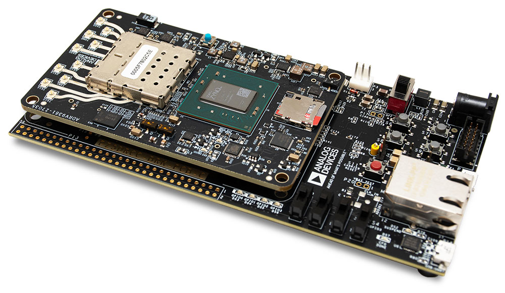
Sounds straightforward, right? However, when it comes to developing an application to run on an SDR, things get more complicated. Let’s consider the Analog Devices ADRV9361-Z7035 [1].

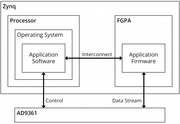
This sports a Xilinx Zynq System-On-Module (SOM) which consists of a dual-core ARM Cortex A9 processor and an FPGA connected internally. The RF Transceiver is an Analog Devices AD9361. To develop an application to run on this SDR, a designer would need:
- An operating system to run on the processor: this manages running software and handles core system functionality such as access to file systems and networking
- To develop software in C/C++/Python to add the application functionality on the processor
- To develop firmware in VHDL/Verilog to implement functionality on the FPGA
- To develop software and firmware to enable communications between the processor and FPGA and then onto the AD9361

Xilinx provides a number of different tools (Petalinux, Vitis, Vivado) to do all of this but, whilst the steps sound simple, each can take a developer weeks of effort!
The Open-Source Component Portability Infrastructure (OpenCPI) framework aims to speed up the development process. OpenCPI provides:
- Component-level development using a set of well-defined interfaces which allows component re-use across multiple platforms.
- Simplified build system where a developer uses a small set of commands and OpenCPI then calls on vendor-specific toolchains as required to build components for a target platform.
- Run-time application control to manage the lifecycle of a running application and provide simplified control.
These aspects can allow a developer to create and run an OpenCPI application without having to write any of their own code (providing suitable components and platform support already exist!).
A Simple Example
The best way to explain the benefits of OpenCPI is with an example. For this, we will create a simple application that reads a set of values from a file, multiplies each value by a constant, then writes the result to another file. We will then run our application on the ADRV9361 SDR described earlier.
A caveat before starting: this example assumes that the developer has already installed OpenCPI and the tools required by their platform vendor of choice. For this example, we use Xilinx Vivado and Vitis. The installation of OpenCPI is covered in its documentation [2].
To develop an application using OpenCPI, we start by breaking down our application into components and define how they are connected. Each component is responsible for a well-defined bit of data processing. In our example, we will use:
- File Reader: this reads data from a file on disk and outputs it to the next component
- Constant Multiplier: this multiplies the data by a constant and outputs it to the next component.
- File Writer: this writes the data it receives to a file on disk.

At this stage of development, the developer does not need to consider where or how the components will be implemented (processor vs. FPGA). Components use the same interfaces regardless of where they are implemented. These interfaces consist of:
- Ports: used to transmit streams of messages. The format and contents of each message is defined by a Protocol Specification and one port can carry a number of different message types defined by opcodes.
- Properties: used for control and monitoring of components. In our example, the constant used for multiplication could be a property.
With the components identified, a developer can then explore existing OpenCPI component libraries to find if they have already been implemented (reducing your own development time!). The File Reader and File Writer components already exist within the OpenCPI Core project [3]. This means we only need to implement our Constant Multiplier component.
To begin development of our application, we create a project to work in with:
ocpidev create project plextek
Within our new project folder we can create a components library with:
ocpidev create library components
We can then create a template specification file for our constant multiplier component with:
ocpidev create spec constant_mutliplier_s_l
Specification files are defined in XML documents in OpenCPI. For our component we have the specification below which has:
- Input port which accepts streams of short (16-bit signed) values
- Short (16-bit signed) multiplier value
- Output port which generates streams of long (32-bit signed) values
<ComponentSpec>
  <!-- Input port -->
  <Port Name="input" Producer="false" Protocol="short_timed_sample-prot"/>

  <!-- Constant multiplier -->
  <Property Name="multiplier" Type="short" Writable="true"/>

  <!-- Output port = input * multiplier -->
  <Port Name="output" Producer="true" Protocol="long_timed_sample-prot"/>
</ComponentSpec>
With the component interfaces specified, an implementation of the component, or worker, can be created. This is the point where a developer should consider if they want to implement their component on the processor or FPGA. In this example we will demonstrate both methods starting with a processor-based or Resource-Constrained C (RCC) implementation:
ocpidev create worker constant_multiplier_s_l.rcc
OpenCPI generates the bare essential code to build the worker as well as a run() method. The run() method is called when data is available on the input and the output can accept new data. We implement our functionality as follows:
RCCResult run(bool) {
    // Get number of input samples and resize output buffer to match
    size_t number_input_samples = input.sample().data().size();
    output.sample().data().resize(number_input_samples);

    // Get pointers to input and output buffers
    const int16_t *input_buffer = input.sample().data().data();
    int32_t *output_buffer = output.sample().data().data();

    // Multiply each input by the multiplier
    for (uint i=0; i<number_input_samples; i++) {
      output_buffer[i] = input_buffer[i] * properties().multiplier;
    }

    // Tell OpenCPI that all ports should be "advanced"
    return RCC_ADVANCE;
  }
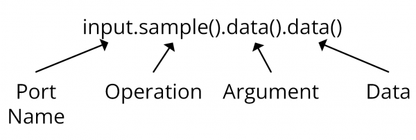
One question that arises from this example is why do we have to use input.sample().data().data() to access the data on the port? The answer comes from the protocol specification mentioned earlier. Our input protocol is defined in the OpenCPI Core project [3] and the section of interest is:
<operation name="sample">
    <argument name="data" type="short" sequencelength="8192"/>
  </operation>
In this protocol we have an operation called sample with an argument of data. This then breaks down as:

With our component written, we can build it with:
ocpidev build --rcc-platform xilinx19_2_aarch32
The xilinx19_2_aarch32 platform uses the C++ compilers provided by Xilinx Vitis to build for the ARM processor of the Zynq.
At this point, we have our worker ready to run on the processor. The next step is to create an OpenCPI application which tells OpenCPI what components are needed and how they are connected. A blank application can be created with:
ocpidev create application constant_multiplier
Applications are defined in XML documents (much like everything else in OpenCPI!) and our example application is shown below:
<Application>
  <!-- File Reader -->
  <Instance Component='ocpi.core.file_read' Connect="constant_multiplier_s_l">
    <Property Name="fileName" Value="input.bin"/>
  </Instance>

  <!-- Constant Multiplier -->
  <Instance Component='local.plextek.constant_multiplier_s_l' Connect="file_write">
    <Property Name="multiplier" Value="10"/>
  </Instance>

  <!-- File Writer -->
  <Instance Component='ocpi.core.file_write'>
    <Property Name="fileName" Value="output.bin"/>
  </Instance>
</Application>
We can then deploy our application to our ADRV9361 by copying the built files across along with the operating system image OpenCPI generates during installation of the platform.
Before we run the application, we have to generate a binary input file with numbers in. We can do this by running:
echo -n -e ‘\x01\x00\x02\x00’ > input.bin
This puts the 16-bit numbers 1 and 2 in the input file (in little endian). We then run:
ocpirun constant_multiplier.xml
At runtime, OpenCPI searches all available component libraries for workers that meet the needs of the application and connects them together – a bit like assembling a jigsaw. After running the application we see an output.bin file appear and examining the file with the hd command we see contents:
0a 00 00 00 14 00 00 00
This is 10 and 20 in hexadecimal format (again in little endian). The output is longer (twice as long in fact) than the input as the output is formed from 32-bit numbers whereas the input uses 16-bit numbers.
To demonstrate how simple it is to achieve the same result on an FPGA we can also create a Hardware Description Language (HDL) worker. We create the worker template with:
ocpidev create worker constant_mutliplier_s_l.hdl
We then create our VHDL implementation of the multiplier:
architecture rtl of worker is
begin
  -- Data on ports and in properties is easily accessed
  output_out.data <= std_logic_vector(signed(input_in.data) * props_in.multiplier);

  -- Output ports are "given" to and input ports are "taken" from
  output_out.give <= input_in.ready and output_in.ready and ctl_in.is_operating;
  input_out.take <= input_in.ready and output_in.ready and ctl_in.is_operating;

  -- Ports use qualifiers to give the validity of the data and position in a message
  output_out.valid <= input_in.valid and ctl_in.is_operating;
  output_out.som <= input_in.som;
  output_out.eom <= input_in.eom;
  output_out.eof <= input_in.eof;
end rtl;
The worker can then be built with:
ocpidev build --hdl-platform adrv9361
As OpenCPI cannot generate an FPGA bitstream at runtime, we have to do a bit more preparation before we run our FPGA worker. We must make an assembly where we will place our worker. Assemblies are very similar in structure to an application and consist of the workers the developer wants, the connections between the workers and any connections to be made outside of the FPGA. We create a blank assembly with:
ocpidev create hdl assembly constant_multiplier
Within this assembly we instantiate our component and declare it to have Externals. External ports are accessible outside of the FPGA assembly and by default are connected to the interconnect between the FPGA and processor on the Zynq.
<HdlAssembly>
   <Instance Worker="constant_multiplier_s_l" Externals="true"/>
</HdlAssembly>
At this point, we run:
ocpidev build --hdl-platform adrv9361
As before, we can copy the build files across to our ADRV9361 and, to prevent OpenCPI using the RCC worker, we can delete its object file. We can then delete the output.bin file and once again run:
ocpirun constant_multiplier.xml
OpenCPI now can’t find our RCC worker so instead loads the FPGA bitstream, connects this to the file read and file write (which still run on the processor) and then runs as before. Simple!
The story doesn’t end here, and OpenCPI offers much more beyond what I’ve discussed in this post! Just one example is the interface that it offers to allow real-time management and control of OpenCPI applications and its workers from a separate C++ program.
So what’s the catch?
This post has focussed on a very simple example of using OpenCPI to perform signal processing on a platform which offers multiple options for where to execute software. It has a number of advantages to offer:
- Encourages component re-use – components can be written and well tested once, reducing wasted development time. Open-source libraries of components already exist online too!
- Developers can construct complex applications using existing components so knowledge of languages such as C++ and VHDL is not required if a component already exists. OpenCPI handles the assembly of the necessary artifacts from the application and assembly XML files provided by the developer.
- Open source – if it doesn’t meet your current requirements, it can be updated or modified and has an active (and growing) community supporting it.
However, given the complexity of the problems it is trying to solve, it of course comes with some disadvantages too!:
- If a platform isn’t already supported then there can be significant effort in adding support. This is lessened if the new platform shares attributes with an existing one (for example, if is based on a Zynq or uses an AD9361) as existing code can be re-used.
- It is still under active development – this means that things are liable to change but also that bugs exist! A developer must be prepared to become familiar with the framework and may also need to get involved with issue reporting to support resolution of issues!
However, it is worth noting that development of the OpenCPI framework has ramped up in the past two years and is now being used by the Ministry of Defence in partnership with industry to create the latest generation of Electronic Counter Measure equipment [4]. This alone suggests that OpenCPI will be around for some time yet.
References
- https://www.analog.com/en/design-center/evaluation-hardware-and-software/evaluation-boards-kits/adrv9361-z7035.html
- https://opencpi.gitlab.io/releases/latest/
- https://gitlab.com/opencpi/opencpi/-/tree/develop/projects/core
- https://www.leonardo.com/en/press-release-detail/-/detail/25-07-2022-leonardo-led-team-wins-41m-contract-to-digitally-protect-bomb-disposal-troops


